|
The Model T FordGenerator
The following page has been written in two parts, depending on the level of information you wish. The first, is a simplified explanation of how electricity is created and includes explanations of such terms as volts, amps, ohms and resistance. Understanding how these work together will help you understand how your generator works and hopefully trouble shoot it when it doesn't.
You can go directly to the generator information here if you prefer. The Theory Let's look at the definitions of some terms used in the explanations of a generator. These are not specific to generators or the Model T.
This is a list you can use to jump down the page to where each is referenced: An amp, short for ampere is a measure of the flow of electricity. Electricity cannot be seen or used to do anything unless there is a flow or current. Electricity does not flow unless there is some force or pressure to make it flow. This is called an electromotive force. A volt, or the voltage) is the name given to the measure of the force that moves electricity. A volt can be created either chemically, through the chemical reactions in a battery, or mechanically, via the actions of a generator. A conductor, is a material that allows the flow of elctricity through it. Different materials have different levels of conductivity. Resistance, is the term used to measure how obstructive a conductor is in allowing electricity to flow through it. The less conductive a material is, the higher the resistance it has. That is, a material that readily allows electricity to flow through it has low resistance as it doesn't obstruct the flow. This resistance is measured in ohms. The best conductor or electricity is silver, followed by copper, then aluminium, zinc, brass, platinum and iron. AC - alternating current DC - direct current. The Model T Ford uses both AC and DC in it's electrical systems, unlike modern vehicles that only use DC. The magneto creates AC and the generator and battery provide DC. AC current alternates its flow from a positive charge to negative charge, where DC flows in a direct path with no alternation and this results from how the current is created. A rule: Current always flows from positive to negative.
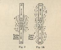
So how does a generator generate current? We need to understand magnetism to understand this. As most people know, a permanent magnet has two "poles" a North pole and a South pole. Because magentism is an an invisible force that flows through a magnet towards the north pole, when two magnets are placed with the same poles to each other, these forced repel against each other, which is why the magnet ends can't be joined. However if two opposing poles are put togther, the "out" flow from the north pole, is attracted to the "in" flow of the other magnet's south pole. These are referred to as permanent magnets as they always remain magnetised. When a closed loop of a conductive material, such as copper wire is passed in way that cuts across the forces of a magnet between it's poles, the resulting action is called electromagnetic induction. This is the force that creates the flow of current in that wire. These principles are used in generators, although with some variation. A generator uses the principle of electro magnetism, in that a magnetic field is created when a current is passed through a wire. Generators use field poles that are mounted inside the case, these are soft iron cores with wire wound around them and insulated. Soft iron does not remain magnetised and is therefore not a permanent magnet, but, it does retain a small amount of magnetism once exposed to a magnetic field. This means that there is sufficient magnetism left in the field poles when the generator is not running, to enable the process to start. Now we must look at the components of a generator.
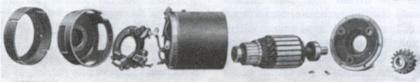
These are the casing, field poles, armature/comutator brush assembly and the necessary bearings and seals. The case is almost always a round cylinder with two end plates and is mounted to the engine which drives it. Inside the case, mounted to it are the field poles, shaped to the contour of the inside of the casing. Next, the armature. The armature is made of a soft iron shaft and has mutliple windings of copper wire. This drum type armature spins, driven by the engine, inside the casing in the middle of the field poles, but not touching them.

As the same wire then passes the other field pole the current is switched from negative to positive. The Ford Model T uses 4 field poles and this increases the magnetic fields that the armature moves through, allowing higher currents to be produced. See figure 3 and the magnetic fields that are produced On one end of the armature is the comutator and it is necessary to understand one more principle before continuing. The field poles in the casing effectively create a north pole on one side of the casing and a south pole on the other. Remembering that as a wire (or in this case, multiple wires) on the armature pass through the magnetic field created by the field pole, a current is made to flow in the armature windings, but, as it revolves past one, it is only doing this temporarily in one direction. This means that the current is switching from + to - and therefore is not direct, DC, but AC. This is of no use for charging a battery, which must have direct current. So how do we convert this AC in the generator to DC? In figure 3, you can see a loop of wire, each end connected to a segment of a commutator. When the left wire (marked 1-2) passes upwards past the N pole of the magentic field, the current is moved in a clockwise direction in the wire from point 1 towards point 4, or negative to positive and therefore to the + brush tocuhing the commutator current in one half rotation of the armature. As the armature completes a full revolution, the other side of the wire loop (marked 3-4) is now passing the N pole of the magnetic field, the direction of the current flow continues towards the + brush. Because the + brush is not in contact with the same end of the wire loop, because there is more than one commutator segment to connect with (one each end of the wire) DC current is produced. A commutator has multiple segments that are each separated by a substance called mica that insulates each segment from each other and the armature has multiple windings to magnify the amount of current produced. Ok, so now we know how the current is produced and "pushed" through the armature wire loops, remembering that the more wire loops and rotations there are, the more current should be produced... So, rememeber that we talked about the field poles and that they were not permanent magnets, but we require a magnetic field to pass the armature wire loops through? Well, with some residual magnetism in the field poles, as the armature revolves, some current is produced. Some of this current is wired to pass through the field poles and in doing so increases the magnetism, increasing the magnetic field, the armature continues to rotate through a stronger magnetic field, creates more current and so on. We need to regulate this process, otherwise, the faster the armature rotates, the higher the current and magnetic field and the generator would eventually destroy itself. There are a number of methods employed to regulate a generator, the Ford Model T generator uses the 3rd brush method. Stick with me here, this bit gets a bit tricky...
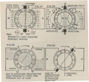
In fig 27, you can see that the magnetic lines of force from the field poles move from North to South.
These are the lines of force the armature "cuts" through to produce current. As the armature does so, the current in its windings creates its own small magnetic field as well (see fig 28, the circles marked R,R1). This field affects the direction of flow of the lines of force.
When this second magnetic field is absent, there is an effective neutral point(neutral line in fig 27) in the magnetic field poles, 90 degrees to the N and S points.
The magnetic field in the armature affects the field pole magnetic lines making dense magnetic areas and weak areas. See fig 29
This "bend" in the magnetic lines shifts the neutral line.(see fig 30)
Because the third brush is used to provide the current supply to the field poles, and therefore create the main magnetic field, it's contact position on the commutator affects the amount of current passed to the field poles. This is turn controls the strength of the magnetic field and thus the amount of current produced through the armature.

Looking at fig 4, you can see that the number of magnetic lines between the negative brush (C) and third brush (E) is 7. As the current through the armature increases as it "cuts" through these lines, its own small magnetic field begins (as we discussed before) and it distorts the main magnetic lines of force, shifting the neutral point and you can see in fig 5 that now there are only 5 lines being "cut" through by the armature between the negative brush and third brush. Less lines, means less current in the armature and therefore the amount of current is controlled. Moving the position of the brush increases or decreases the effective number of lines "cut" through as the armature revolves and therefore the amount the generator produces.
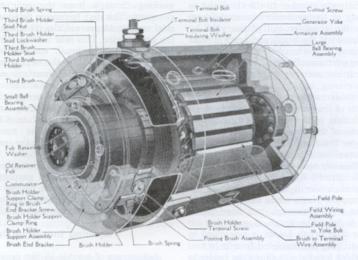
Model T Ford Generator Animation The Model T Ford Generator is known as a shunt type, using third brush regulation of the charge rate, a series wound armature and four field coils/poles that are mounted in and to the outer generator casing. The armature is suspended by bearings at either end of the armature. The front of the armature supports the drive gear which is held in place on the armature by a pin and the brush holder is mounted to the rear casing cover. A cut out is generally mounted on top of the generator, one side connected to the generator output terminal, the cut out earthed to the generator casing and the other connection providing an output terminal to which the car wiring loom is connected, providing a link to the battery. WARNING: this side of the cut out is live whenever the battery is connected so take care not to short it out! The generator gearing is set to run off the timing gear of the engine, so that at an average speed of 20mph, the generator is running at about 1200 rpm. It is at this speed that the generator produces it's optimum output. The purpose of the cut out is to disconnect the battery from the generator when the generator is not operating, or operating at a speed sufficient to charge the battery. If the cutout did not exist, whenever the generator output was lower than the battery, the generator would drain the battery flat. The third brush regulation is achieved by setting the position of the third brush on the brush ring in a position that restricts the level of current able to excite the field coils and therefore preventing the generator charge amount from continually increasing above the required amount. Failure of the generator is usually detected when the ammeter shows no or insufficient charge. There are a number or potential causes of generator failure: Electrical -
Mechanical -
For technical help on testing, repairing and adjusting the Model T Ford Generator and Cut-Out see the Members' only "How to" pages that are coming soon.
Acknowledgment:The diagrams and technical images on this page are courtesy of the MTFCA and Dykes Automotive Encyclopaedia. Colour images are the property of Modeltcentral.com Return to Model T Ford Technical here
|