|
The Model T Ford Ignition& its timing
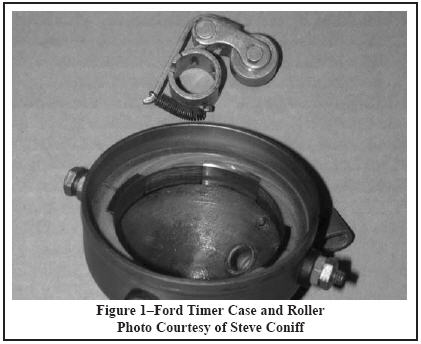
The following is an article on the Model T Ford Ignition System and its timing, written by Ron Patteron & Steve Coniff. For those unfamiliar with the authors, Ron Patterson is a widely accepted expert on the Model T Ford Ignition and often assists enthusiast in trouble with all things ignition. I have been fortunate to receive assistance from Ron on a few occasions and am very gratefull for his assistance with some of the electrical articles on this site. With the possible exception of the planetary transmission, no part of the Model T Ford’s original design is more commonly misunderstood than the magneto ignition system. The purpose of this article is to simply explain how the Model T Ford ignition system and associated spark timing actually work. Figure 1 is an original Ford timer case and roller. This
is important because there were many different manufacturers
of timers other than Ford and they vary significantly in
mechanical design and construction. The Ford timer case
can be usually identified by the word “Ford” in script
stamped into the main case near where the pull lever is
affixed and the roller has similar markings on the spring
loaded roller support arm, see Figure 2. The timer case has
four electrical conductive metal segments mounted in a non-metallic insulator at equally spaced intervals around the
inside circumference of the case. Each conductive segment
has an insulated screw that extends outside the case
perimeter forming a screw terminal with thumbnut where
wiring to the coil box can be connected. The timer roller is
mounted on the end of the camshaft, indexed with a pin and
retained by a locking nut. The roller rides on the inner
surface of the timer case connecting engine ground to each
conductive segment as it rotates thereby completing the
electrical circuit to each coil.
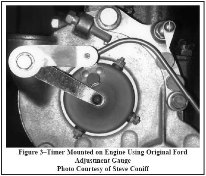
Figure 3 shows the timer mounted on the engine and the
original Ford adjusting gauge used to set the timer at 2.5 inches from the adjacent front plate mounting bolt. With the
spark lever fully retarded (all the way up) the timer pull rod
is appropriately bent to insert the end of the rod into the
timer lever hole without changing the 2.5-inch
measurement. As the steering column spark lever is moved
through its quadrant, which consists of 28 notches, the timer
case moves through its range of movement advancing the
spark at a rate of approximately 2.85 crankshaft degrees per
notch. This relationship is not exactly linear because of the
angle of the pull lever on the end of the spark rod.
For the purposes of this discussion it is important to
understand the basic electrical characteristics of the
magneto output. The magneto output is an AC signal of
varying voltage, frequency and current with eight complete cycles for each crankshaft revolution. The voltage varies
over the normal range of engine speed from a low of 4 volts
to a high of over 30 volts with sufficient current capacity to
operate the coil. The sixteen positive and negative peaks of
this signal are separated by 22.5 degrees of crankshaft
revolution. The significance of this last point will be
explained later.
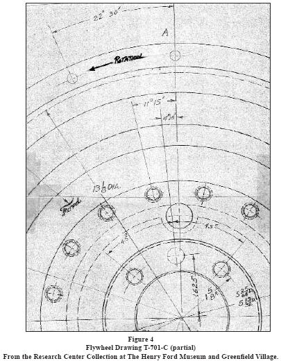
Figure 4 shows a portion of Model T flywheel drawing
T-701-C (viewed from the transmission side). If you study
this drawing carefully you will see the magnets are mounted
on the flywheel in such a way that the magneto output is
advanced from Top Dead Center (TDC) by 7 degrees of
crankshaft rotation. (11 Degrees 15 Seconds minus 4
Degrees 15 Seconds equals 7 Degrees) The significance of
the magnet mounting will be explained later. The Record of
Changes for the flywheel drawings indicate the magnet
mounting was unchanged for all Model T production.
The construction of the Model T ignition coil is well
understood and will not be described in further detail here.
For the purposes of this discussion it is important to understand that proper
operation of the coil points will affect ignition timing and
hence engine performance. Additionally, the ignition coil
operates entirely different when running on battery as
opposed to magneto. When a properly adjusted ignition coil
is running on battery and the roller grounds the timer
segment, the coil will vibrate continuously and provide
voltage to fire the spark plug. When a properly adjusted
ignition coil is running on magneto and the roller grounds
the timer segment the coil points respond to the individual
current pulses of the magneto output to fire the spark plug.
To reliably and consistently respond to the individual
magneto current pulses and maintain accurate ignition
timing the coil points must be carefully adjusted. The only
way correct point adjustment can be attained is by using a
hand cranked coil tester which simulates conditions very
similar to that which occur in the Model T ignition system
when running on magneto.
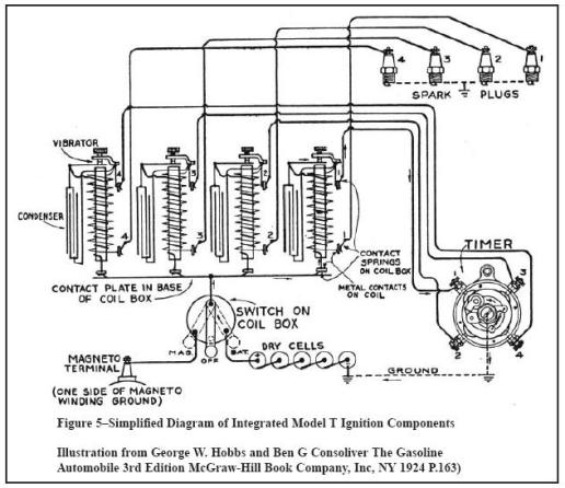
Figure 5 is a simplified diagram of all the various
ignition components integrated together as a system.
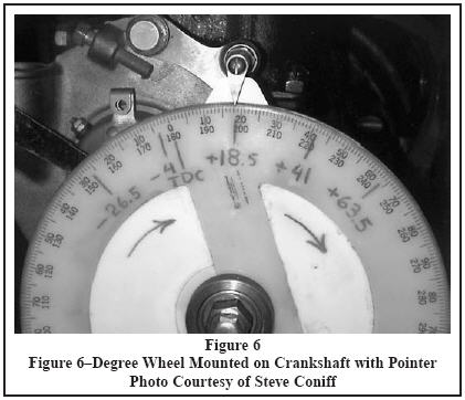
Now lets discuss the detailed spark timing measurements
we took. Figure 6 depicts the method used to take the annular
degree measurements. Remember, wherever the word
“degree or degrees” is used hereinafter it is understood to
mean “crankshaft degrees of rotation”. A degree wheel was
mounted on the end of the crankshaft with a stationary
marker pointing to the scale. TDC was located on cylinder
one, the degree wheel indexed so the marker pointed to “0”
degrees and fixed so the inter-relationship would not change
as the crankshaft was rotated.
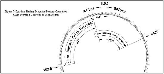
Figure 7 is a diagram depicting the first set of measurements.
The engine front plate was checked for concentricity
with the end of the camshaft. A reground Ford camshaft,
good original Ford timer case and NOS timer roller were
used to take these readings. The timer case was positioned
using the Ford gauge. By manually rotating the crankshaft it
was determined that the timer segment was grounded at 15.5
degrees after TDC and remained grounded for 87 degrees.
As the timer case was moved through its range of the spark
lever quadrant it was found the total advance of the timer
case was 80 degrees.
As previously mentioned, when operating on battery,
the ignition coil will vibrate continuously firing the plug as
long as the timer segment is grounded. As you can see in
Figure 7 the coil will continuously fire the spark plug
starting at 15.5 degrees after TDC and cease at 102.5
degrees after TDC. As engine speed is increased and the spark lever advanced the coil will fire the spark plug throughout the degree range of the timer case movement until it reaches maximum advance of 64.5 degrees before TDC.
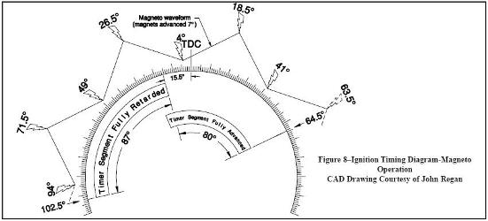
Figure 8 is a diagram depicting the second set of measurements.
The test set up is unchanged and the intervals of
timer segment and timer case movement are the same.
When taking these measurements a properly rebuilt Model
T coil was electrically connected to the timer, magneto and
spark plug and the engine rotated at 600 RPM. An
automotive ignition timing light was connected to the spark
output to read the position of the degree wheel pointer to
determine exactly where the coil fires in relationship to
crankshaft position.
The magneto waveform depicted in Figure 8 is representative
only and does not reflect the shape of the magneto
waveform when viewed on an oscilloscope. But it does reflect the timing relationship attained by advancing the
magnets on the flywheel by 7 degrees as indicated on
flywheel drawing T-701-C. The spark symbols show the
points where the ignition coil will fire on the magneto
current output with respect to piston travel. Each of these
locations is logically separated by 22.5 degrees.
When starting the Model T engine on the magneto with
the spark lever fully retarded, the coil initially fires at 26.5
degrees after TDC. This is the nearest location based upon
the timer case (spark lever) position where sufficient
magneto current output is available. As engine speed is
increased and the spark lever advanced the coil will initially
fire at one of the additional locations where sufficient
magneto current output occurs. These locations are 4
degrees after TDC, 18.5 degrees before TDC, 41 degrees
before TDC and possibly 63.5 degrees before TDC. The
spark depicted at 63.5 degrees before TDC spark may not
occur depending upon the travel of the spark lever past the
end of the quadrant.
Figure 8 helps explain why it is easier to start a Model
T on magneto when the spark lever is advanced a few
notches. By advancing the spark lever the coil will fire at 4
degrees after TDC. If the magnets were not advanced 7
degrees the coil would initially fire at 11.25 degrees after
TDC.
Figure 8 also helps explain why the engine sometimes
speeds up when switching from battery to magneto. There
are locations of spark lever setting when running on battery
that will result in more optimal spark timing when switched
to magneto.As you can see in Figure 7, when running on battery,
linear spark timing can be obtained by moving the spark
lever. This would appear best for optimum engine
performance, but Model T coils do not work well on the 6
volt battery at higher engine speeds.
As you can see in Figure 8, when running on the
magneto, timing advance is not linear. The spark lever is a
selector that, when moved, determines the magneto current
pulse where the ignition coil will supply spark voltage to the
plug.
Get this articleIf you'd like a pdf copy of the original of this article, click below
|